Easy steps to guide you to design your cleanroom monitoring system accrding to current ISO 14644 Standards and GMP Annex1 Regulation.
In order to design your regulatory-compliant cleanroom monitoring system, here we suggest you simple and self-explanatory steps. We can narrow this list down in 4 stages. Planning, System Design, System Installation and System Use & Maintenance. Please note that this article focuses on cleanroom non-viable particle monitoring system in general. However, many points can be applied into viable monitoring.
Written By : Hasim Solmaz
This article published in Cleanroom Magazine September 2019 Edition
How to Plan Cleanroom Monitoring System?
Know your Industry Standards and Guidelines
Current standards and regulations can give you detailed information about your cleanroom monitoring system needs and its solutions. Here are list of standards and guidelines available today;
1. ISO 14644-2:2015 : Cleanrooms and associated controlled environments -- Part 2: Monitoring to provide evidence of cleanroom performance related to air cleanliness by particle concentration
This is the only standard available in ISO regarding monitoring of air cleanliness by particle concentration. Updated 2015 version is now offering a risk based approach with a section about “Creating, implementing and maintaining a monitoring plan”.
2. EU GMP Annex 1 : The Rules Governing Medicinal Products in European Union.
EU GMP Annex 1 has a section called “Clean room and clean air device monitoring”. This section offers several information about requirements and how to achieve this.
3. FDA Guidance for Industry Sterile Drug Products Produced by Aseptic Processing
In this industry guideline, FDA offers intensive information regarding Environmental and particle monitoring in seperate chapters.
4. World Heath Organization (WHO) Environmental Monitoring of Clean Rooms in Vaccine Manufacturing Facilities.
Even if this document looks specific to vaccine manufacturing, you will find several information about routine monitoring and sampling plan.
5. PDA Technical Report (TR) No.13R ; Fundamentals of an Environmental Monitoring Program
PDA offers very useful Technical Reports and TR-13R is one of the best document to achieve proper monitoring plan. Not only summarizes requirements that you need to follow but also offers you a sample plan and examples.
Addition to this standard and regulations, there are reference documents available in PDA, ISPE and local authorities that you are audited by.
Do your Pre-Risk Assessment.
Risk assessment is the most ciritical step to plan and achieve the right monitoring solution. As described in ISO 14644-2, selection of an appropriate risk assessment tool (HACCP, FMEA, PHA, FTA, HAZOP ETC) will be our first step. In general, we are using HACCP (Hazard Analysis and Critical Control Points) to define all non-viable monitoring critical control points and FMEA (Failure Mode and Effects Analysis) to list urgency of this critical monitoring points and their ranking based on your accept/reject criteria. ICH 9 Quality Risk Management document will help you to prepare your execution roadmap.
One note here, during FMEA, you will score your probability and severity first. For probability, you should ask yourself “What is the probability of having particle/s at this location that will harm our product which will end up affecting patient health?”. For example, if we are talking about turn table after depyranization tunnel, your containers are open to ambient air and any failure in your HVAC or personnel interfere will end up with having particles inside your “sterile” product containers. For this particular location, your probability is always high. With the same approach, you will score your severity. Severity here means “what if I have particles inside my container? How it will end up” Result will be catastrophic, right? So, your severity is, again, high. High probability with high severity puts you on LEVEL-1 risk level. This LEVEL-1 will be your main focus to reduce your risks.
Define Your Sample Locations
After defining your risks with proper pre-risk assessment study, next step should be defining your sample location. To reduce your risks, you will start from highest risk locations to lower risk zones.
In general, sterile pharmaceutical manufacturing facilities has following locations to be considered as high risk locations;
1. After Tunnel Exit / Turn Table,
2. Point of Fill,
3. Stoppering
4. Product transfer hatches / window (for semi-stoppered lyophilized products),
5. Transfer CART’s from/to Lyophilizer,
6. Lyophilizer Loading,
7. Capping Zone (in order to reduce risk due to poorly closed stoppers after lyophilization)
8. Room Grade B (No. Of location can be 1 or 2 based on product, personnel flow and room design),
9. Autoclave, sterilizer exit to Grade B areas.
10. Sterile / aseptic manipulation zones such as aseptic connection and under LAF, Grade A.
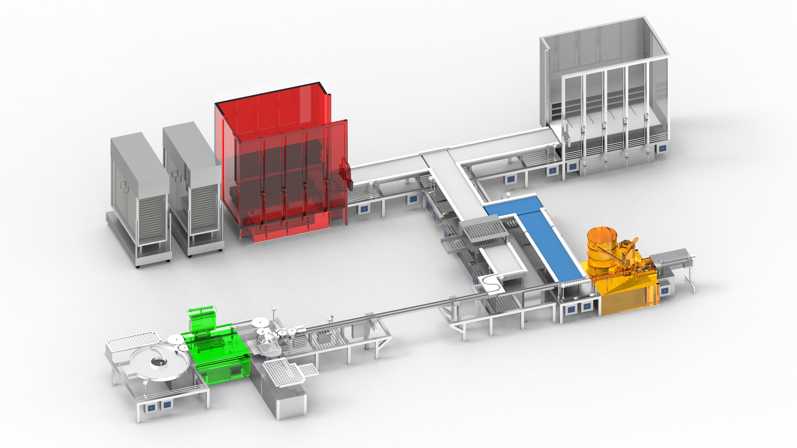
Picture : Pharmaceutical Sterile Manufacturing Process with lyophilization stage & particle monitoring
Critical parameters here are;
• Defining critical location for each isokinetic sampling probe
Being close as possible to risk location is our main motivation here. As per FDA Aseptic Processing Guideline; “representative locations normally not more than 1 foot (30cm) away from the work site, within the airflow, and during filling/closing operations”. Please note, this 30cm is like a sphere centering your isoprobe. In other words, your 30cm distance could be lower or higher than your isoprobe, depending on your application. Container size, distance from surface, operator intervention and possible moving parts should be considered too. In some locations such as capping stations, powder filling points and ampoule closing flame area, distance could be more than 30cm, especially as vertical distance to protect your particle counter and not to sample material itself (chemical powder, glass flakes, aluminium dust etc).

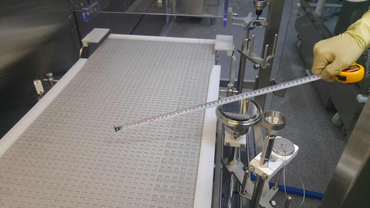
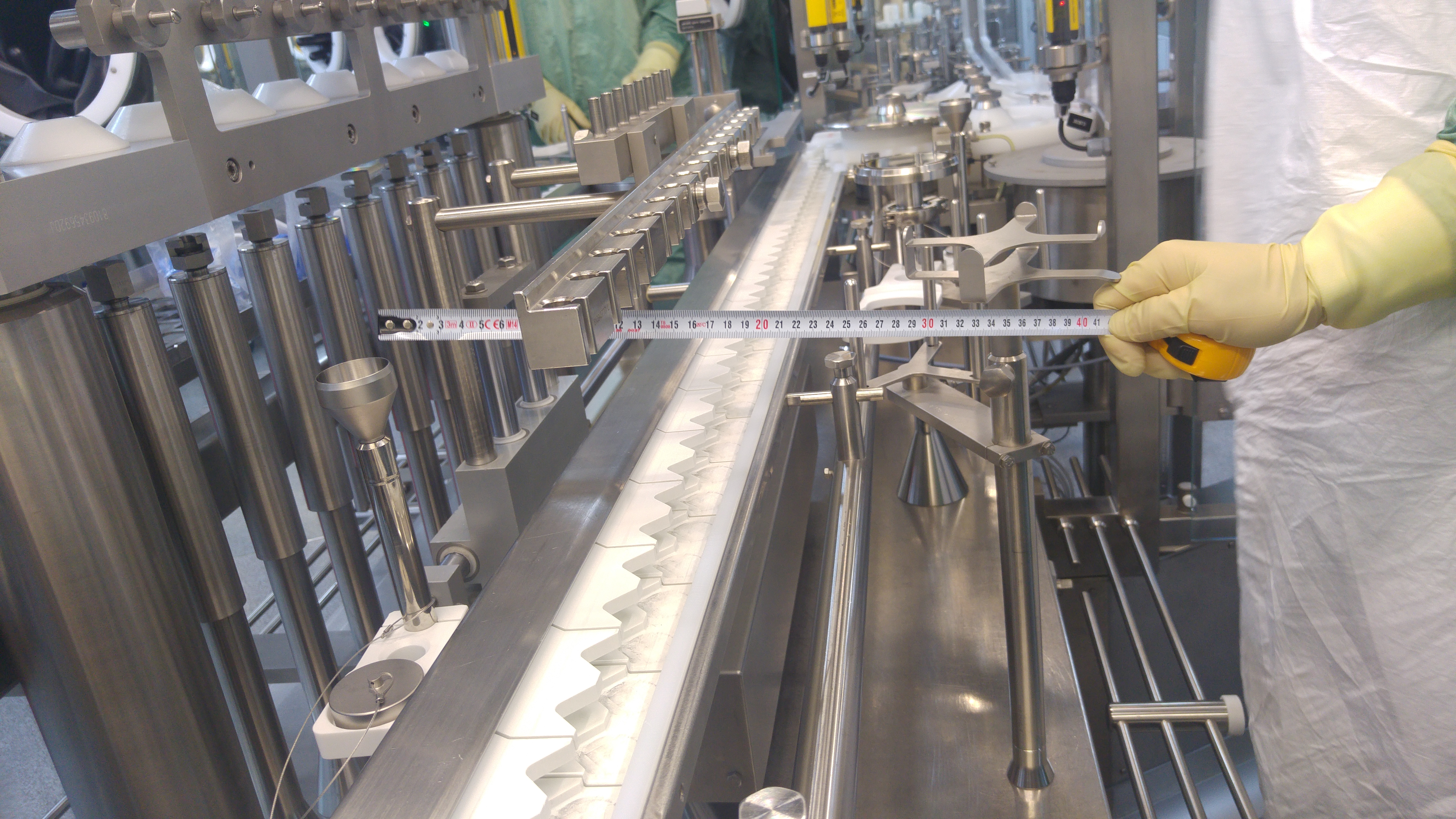
Picture : Non-viable izokinetic sampling probe located near by stopper hooper within 30cm.
• Distance between your sample point and your online particle counter,
Although you are using special tubing for particle sampling between isoprobe and your online particle counter, particles larger than 1 micron may be trapped by your sampling tube depending on radius and number of bends with their bending degree. Best practice here is to place your particle counter close enough (if possible, right under of your sample point) so particles will not be lost due to travel distance and curves inside tubing. Maximum lenght here was defined by ASTM F50 as “size range ' for the particles in the size range between 2 μm to 10 μm, a maximum transit tube length of 3 meter can be used”. ISO 14644-1:2015 defines distance between portable particle counter and isoprobe as “For sampling of particles larger than and equal to 1 μm, the transit tube length should not exceed the manufacturer’s recommended length and diameter, and will typically be no longer than 1 m in length”. Even if this 1 meter definition is good for monitoring locations, this definition is for cleanroom classification routine, not for cleanroom monitoring. Sample tube sent by the manufacturer along with portable particle counter is quite long and users never cut this long tube before starting cleanroom classification. So, you can see spiral shape sample tube all around the cleanroom. Most probably, this operators are losing most of the 5 micron particles inside this swirl sampling tube. For online monitoring, we are using this sample tubes inside stainless steel tubes so there will be solid sampling line with controlled bending radius (Again, according to ASTM F50 “If a flexible transit tube is to be used, then no radius of curvature below 15 cm shall be used”). This can help us avoid flase counts due to probe penetration and uncontrolled sample tube shape and radius.
• Make an engineering study if necessary
Some of your locations may require additional investigation. Especially if you need more statistical data between different sample points for the same risk location. Mobile lyophilizer transfer CART’s can be a nice example here. Between each tray it seems identical. However, clean air supplied by HEPA filter may act differently between ach tray. So, using portable particle counter and collecting data to see if they are all identical is a good practice and an example for engineering study. This can be applied for selecting Room Grade B sampling location between several different options. Most of the time, focusing on return air area and busy areas for operators is a good approach.
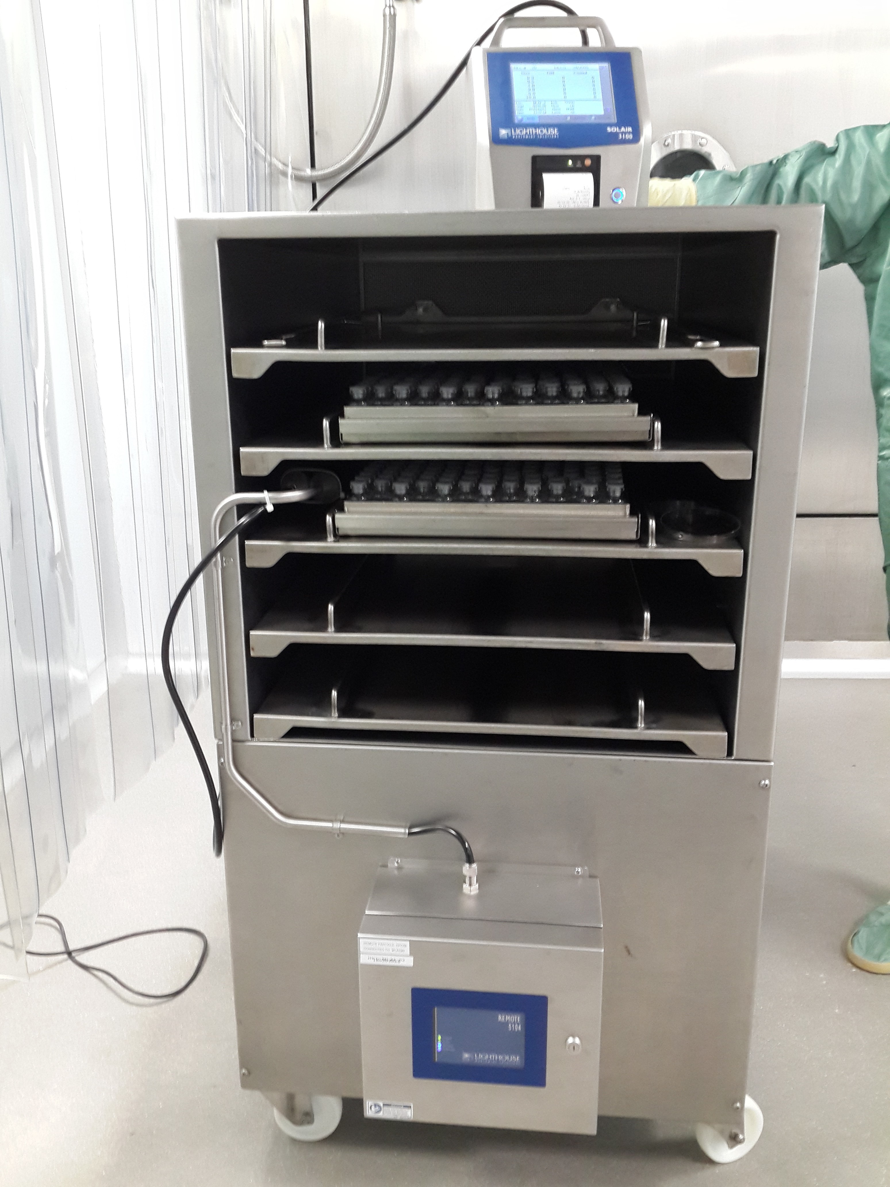
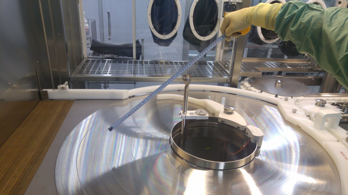
Picture : Engineering study for mobile Lyophilization Loading CART to verify correct location with scientific data.
• Select the most suitable solution for your application
There are different options available for particle monitoring. Built-in pump particle counters or external vacuum systems, analog or digital sensors, with or without display etc. Most important feature here is self diagnostics. Your particle should not only collect one way data, but also communicate with you in terms of flow status, laser health, internal parameters such as background voltage and cal due date reminer. This will help you to understand what is going on with your device before sending it to calibration once in every year and end up getting “your particle counter is deaf and we don’t know when it happened”. This will put you and your entire data in the recent year into a very rough situation. In addition to this, monitoring parameters such as flow rate, sensor health and laser status are critical to maintain data integrity.